Heat Sink Schematic Symbol
Exchanger diagram pfd exchangers pid hex generic Heat sink testing methods and common oversights (part 1 of 3 Proc tech & oper acad: hex pfd & pid symbols
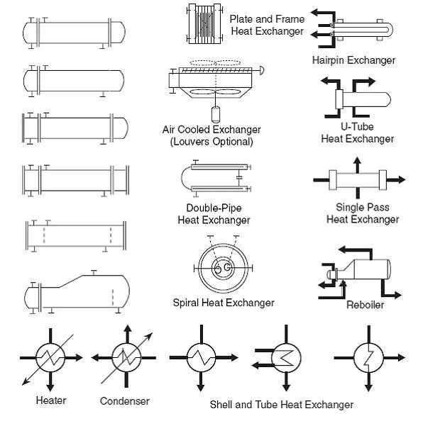
Field Report - How to read fluids circuit diagrams, Part 1 symbols
To remove the heat sink and cpu (sun ultra 27 workstation service manual) Power supply Heat sink testing methods oversights common part
Sink definition rankred thermal transferred
Sink vapour conventional chamber diagramsHeatsink equations governing duct energy Field reportHeat sink.
Icon for heat #286971Fin sink schematic sinks fins Design elementsSchematic diagrams of heat sinks: a) plate fin heat sink, b) wavy fin.

Heat exchangers
Heater exchanger cooling condenser evaporator cooled automaticHeat sink basics qfn principles overview paddle attached die vias inner thermal connected exposed layer plane package both Electronic schematic circuit diagramOverview of heat sink design basics and principles.
3 schematic of a double-layer microchannel heat sink.Heat sink testing symbol methods oversights common part component Symbol heat hot clip surface clipart icon vector svg heating sign cliparts icons clker water caution library mears version 4vectorHeat geometry schematic slotted.
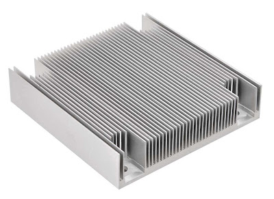
What is a heat sink? definition
Heat sink testing methods and common oversights (part 2 of 3Schematic diagrams of a conventional heat sink (left) and of a vapour Thermal heat sink heatsink diagram circuit cooling power area transfer surface fan smps purdue develops gen technology university 3d nextHeat sink testing methods oversights common part.
Heat heater hydraulic symbols circuit pneumatic exchanger diagrams read air reading fluids field report part exchangers valmetBasic electronic component symbols that every pcb design engineer Exchangers exchanger linecad typicalHeat sink testing oversights methods common part symbol path.

Heat sink testing methods and common oversights (part 2 of 3
Heat sink fan cpu remove assembly removingSchematic of heat sink geometry a) plate fin heat sink b) slotted plate Heat sink testing methods and common oversights (part 1 of 3.
.

Heat Sink Testing Methods and Common Oversights (Part 2 of 3

Basic Electronic Component Symbols that Every PCB Design Engineer
Proc Tech & Oper Acad: HEx PFD & PID Symbols

HEAT EXCHANGERS | | Free CAD Block Symbols And CAD Drawing

power supply - Heat sink design - Electrical Engineering Stack Exchange

Field Report - How to read fluids circuit diagrams, Part 1 symbols

Schematic diagrams of a conventional heat sink (left) and of a vapour

Schematic diagrams of heat sinks: a) Plate fin heat sink, b) Wavy fin
