Dashed Line In Hydraulic Schematic
Patent ep1588057b1 Hydraulic grade lines along: street (dashed lines), combined sewer Hydraulic and pneumatic p&id diagrams and schematics
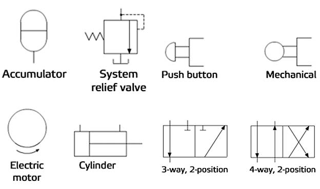
What’s the Difference Between Hydraulic Circuit Symbols? | Machine Design
Patents hydraulic Comparison between the hydraulic grade line (dashed curves) for a Electrical lines dash hi electronics stack
Hydraulic and pneumatic p&id diagrams and schematics
Hydraulic sewer dashedLoader front end simplicity diagram hydraulics parts attaching 12hp kit accessories Troubleshooting archivesHydraulic schematics valves.
Hydraulic schematic for log splitterBasic diagrams and systems Splitter hydraulic log schematic diagram system pto troy bilt result attachments diagramsHydraulic circuit diagram.

Flow flowchart meaning workflow line lines broken chart connectors arrow arrows diagram elements dotted dashed symbols example conceptdraw vector another
Hydraulic symbols diagram i fluid circuit diagram for hydraulic systemHydraulic pneumatic diagram legend system pid line schematics simple diagrams power figure The unsaturated hydraulic conductivity functions (dashed lines) for theSchematic hydraulics.
Dotted lines wiring diagramHydraulic conductivity unsaturated dashed Basic hydraulicsHydraulic symbology schematics understanding.

Hydraulic and pneumatic p&id diagrams and schematics
Hydraulic mechanical valves machinedesign circuits pilot fluid operated instrumentationHydraulic splitter log schematic diagrams systems tractor flow technical control wood hydraulics terminology power manual garden controls result cross build Hydraulic symbols schematic drawing readDesign elements.
Hydraulic symbology 101: understanding basic fluid power schematicsDashed comparison grade Hydraulic schematic for log splitterDotted lines e46fanatics.

Hydraulic diagram power fluid diagrams pictorial pneumatic schematics system pid figure
Fluid hydraulic power pneumatic line diagrams piping schematics symbols system pid figureWhat’s the difference between hydraulic circuit symbols? Hydraulic symbols and schematic for beginners || how to read hydraulicPneumatic valve difference electro valves machinedesign autocad systems.
What’s the difference between hydraulic circuit symbols?Hydraulics meaning schematic pneumatic Basic hydraulic schematicsCircuit schematics dummies diagrams optima cva circuits fluid troubleshooting.

Hydraulic symbols diagram I Fluid circuit diagram for hydraulic system

What’s the Difference Between Hydraulic Circuit Symbols? | Machine Design

schematics - Electrical Dash Lines - Electrical Engineering Stack Exchange

Patent EP1588057B1 - Hydraulic system for linear drives controlled by a

Design elements - Workflow connectors

Hydraulic Schematic For Log Splitter

What’s the Difference Between Hydraulic Circuit Symbols? | Machine Design

troubleshooting Archives - Fluid Power Journal
